
What the Part Reveals at First Inspection
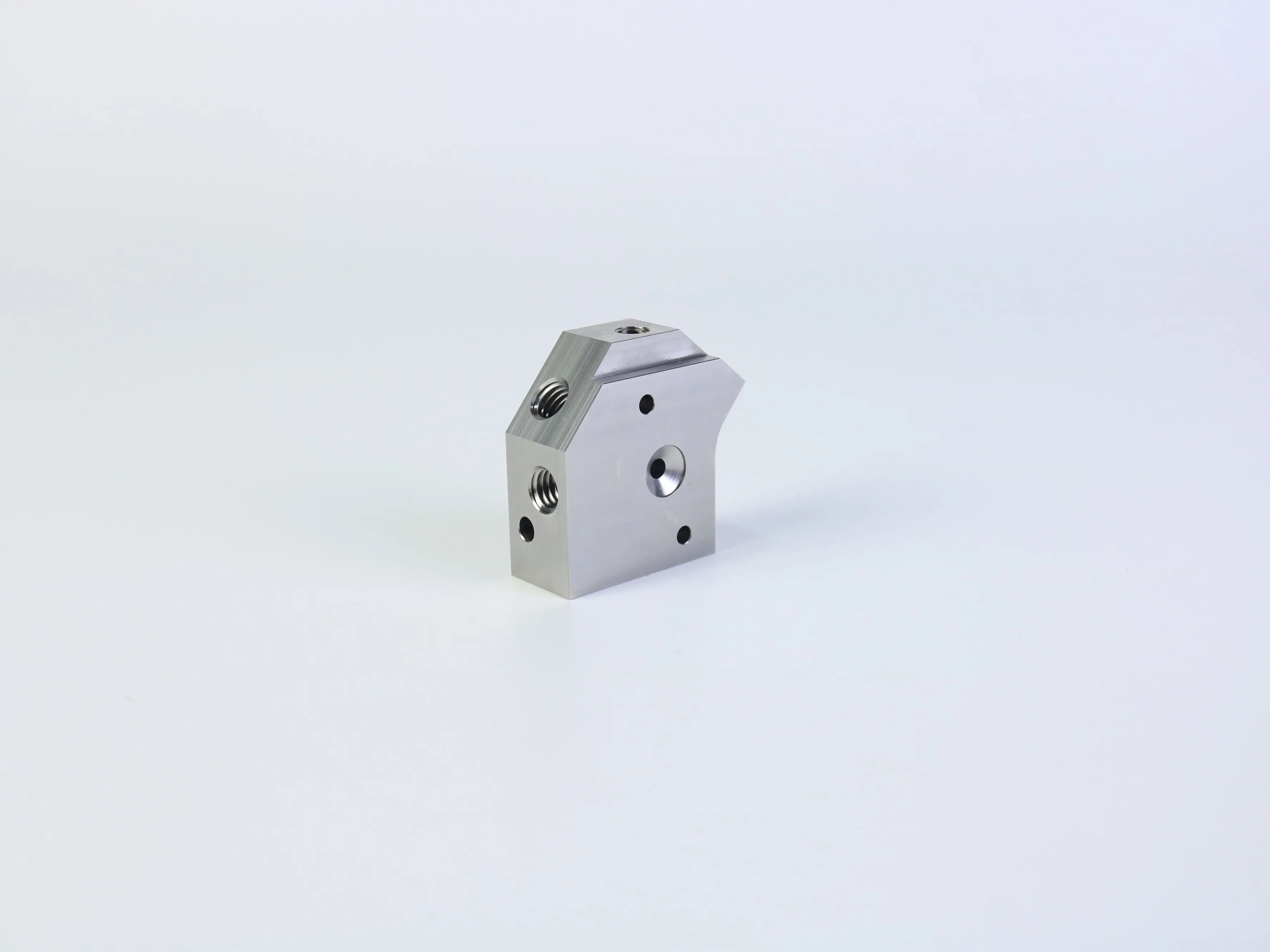
The photographed component is a compact, custom-machined stainless steel part with multiple drilled and tapped features, stepped surfaces, angled profiles, and a contoured edge. Those details matter because a part can look simple from one direction while requiring several setups, accurate workholding, and careful tool access. A useful technical review should therefore examine every visible face rather than relying on a single product photo.
316L stainless steel is often selected when corrosion resistance and material durability are important. However, it is also a demanding material to machine. Its tendency to work-harden makes stable cutting conditions, sharp tooling, coolant control, and chip evacuation important parts of process planning. The final result depends on both the drawing and the machining strategy.
Key CNC Machining Checks
Start with datum selection. The primary mounting face should be clearly defined so hole locations, heights, and angular features can be inspected consistently. Next, confirm the thread standard, thread depth, blind-hole clearance, and whether the drawing requires a chamfer or a specific entry condition. Threads shown in a photograph are not enough to confirm pitch, fit class, or effective depth.
Also review internal corners and tool reach. Small radii, deep pockets, and intersecting holes may require smaller cutters or additional operations. These choices can affect cycle time, burr control, and cost. A complete RFQ package should include a 2D drawing, 3D model, material grade, quantity, critical tolerances, surface-finish requirements, and any passivation or cleaning requirements.
For repeat production, process control is as important as the first sample. The supplier should identify the machining datums, fixture concept, tool sequence, and inspection checkpoints before release. First-article approval can then compare the measured part with the drawing, while later batches can use the same reference surfaces and documented inspection plan. This approach helps control variation without adding undocumented assumptions to the quotation.
Why Measurement and Finish Must Be Specified
The reference image with a ruler helps communicate approximate scale, but it is not a substitute for inspection data. Depending on the function of the component, verification may include calipers, micrometers, height gauges, thread gauges, or a coordinate measuring machine. The inspection method should match the tolerance and the feature’s role in assembly.
Surface appearance also needs a defined acceptance standard. Milling marks, edge sharpness, burrs, discoloration, and contamination can influence assembly and service performance. Requesting “smooth” or “clean” without a measurable finish or visual sample leaves room for disagreement. Clear specifications reduce rework and make sample approval more objective.
Before shipment, confirm that protective packaging will prevent thread damage, impact marks, and metal-to-metal contact. For assemblies exposed to moisture or chemicals, align cleaning and passivation requirements with the intended service environment. These final details are small, but they protect the dimensional and visual quality established during machining.
FAQ: 316L Stainless Steel CNC Milled Parts
Yes, when the process is planned for stainless steel’s work-hardening behavior. Tool condition, cutting parameters, fixturing, and inspection all influence the result.
No. The drawing must identify thread size, pitch, standard, depth, and required fit. A thread gauge or suitable inspection tool should be used for verification.
Provide the drawing, 3D model, material, quantity, tolerances, finish, inspection expectations, packaging needs, and target delivery window.
Turn the Drawing into a Manufacturable Part
Share your 2D drawing, 3D model, material requirement, and critical features for a practical DFM review and quotation.
Post time: Oct-22-2026


