
Why This Component Requires More Than Simple Cutting
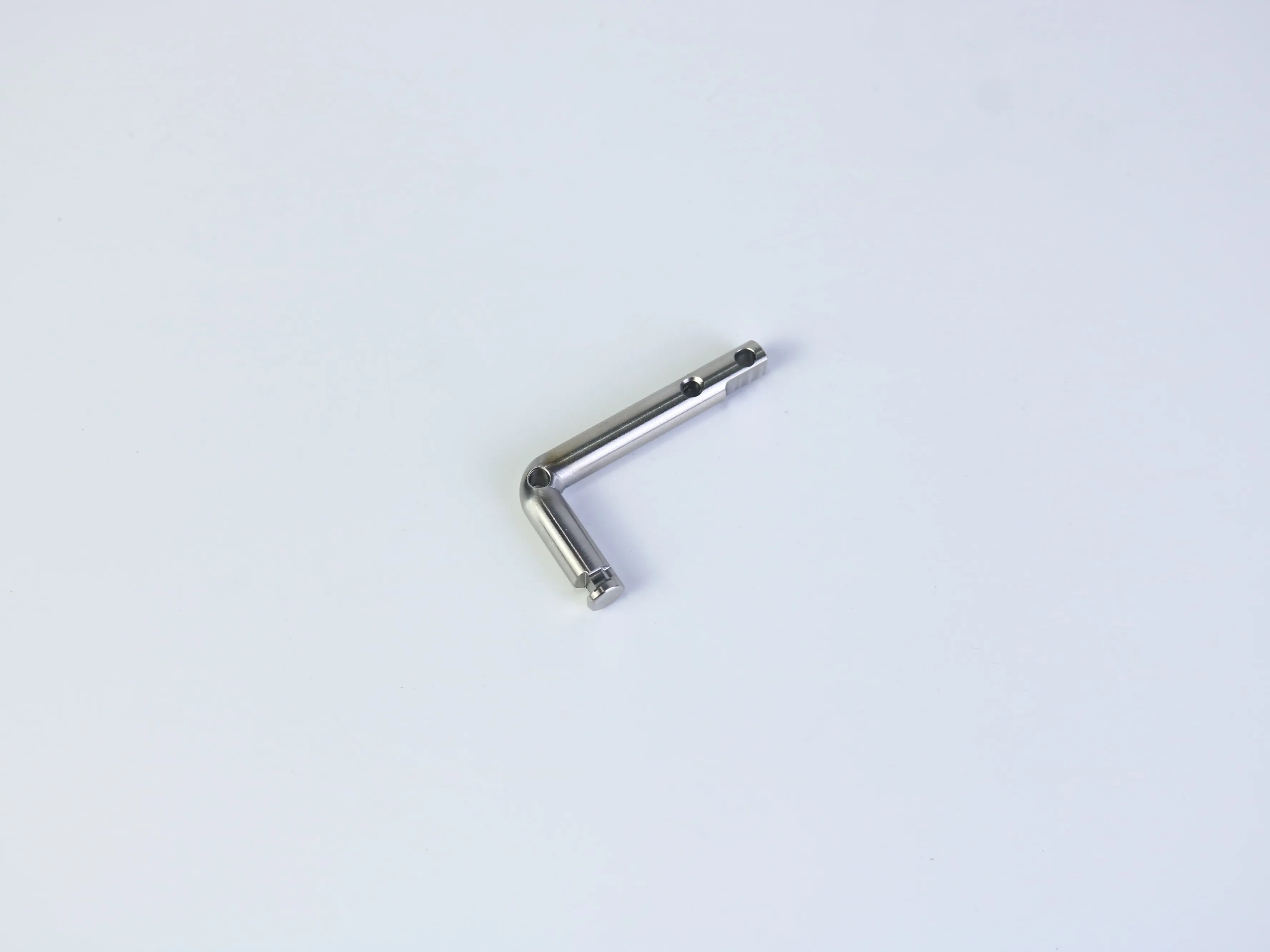
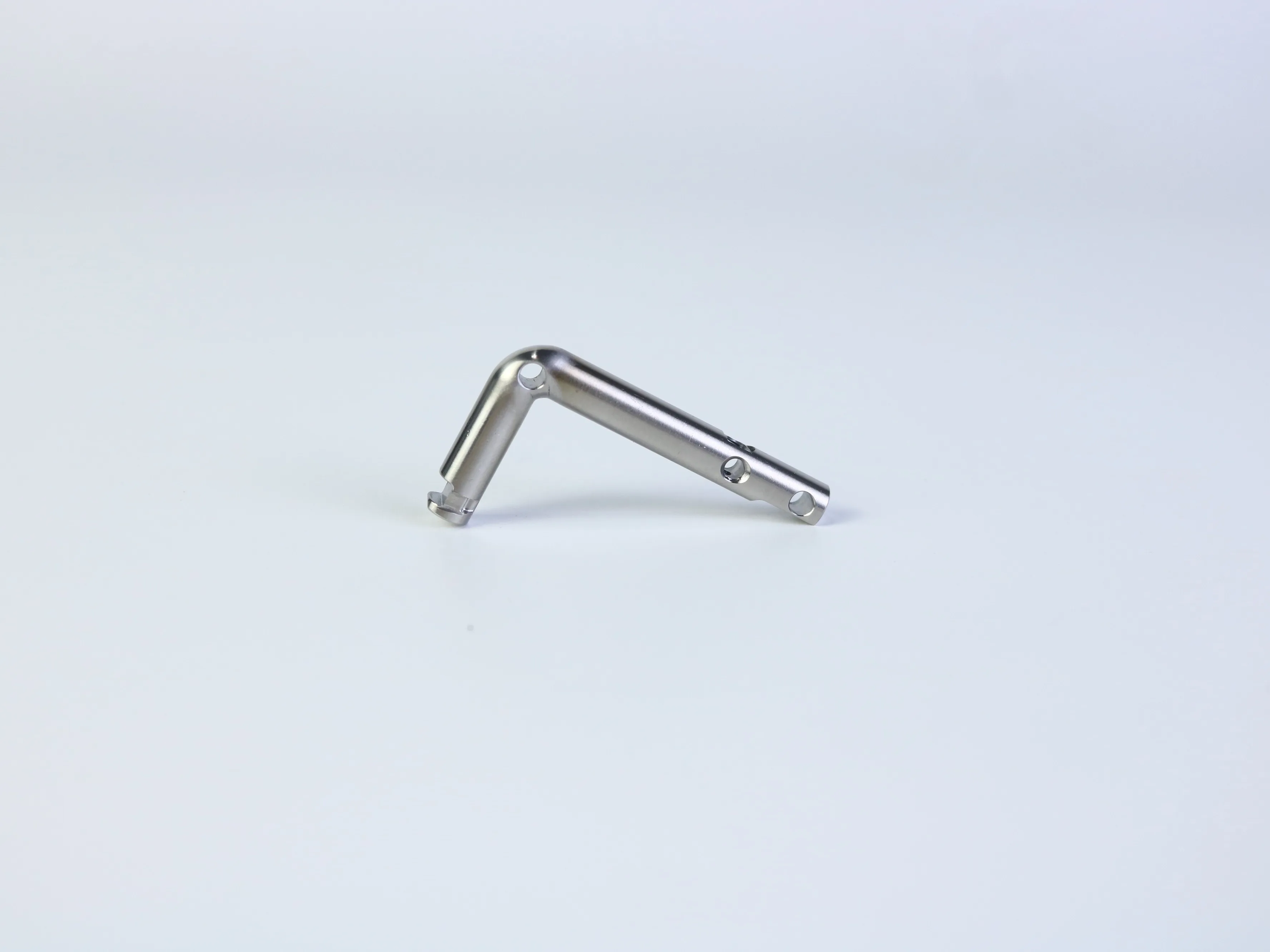
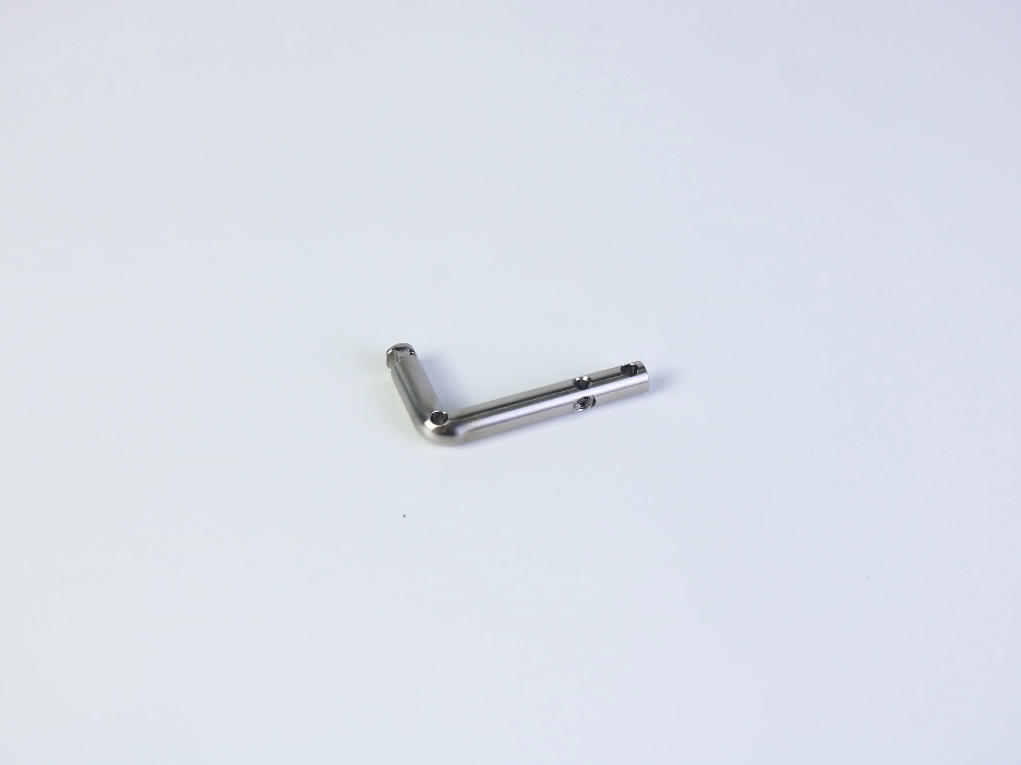
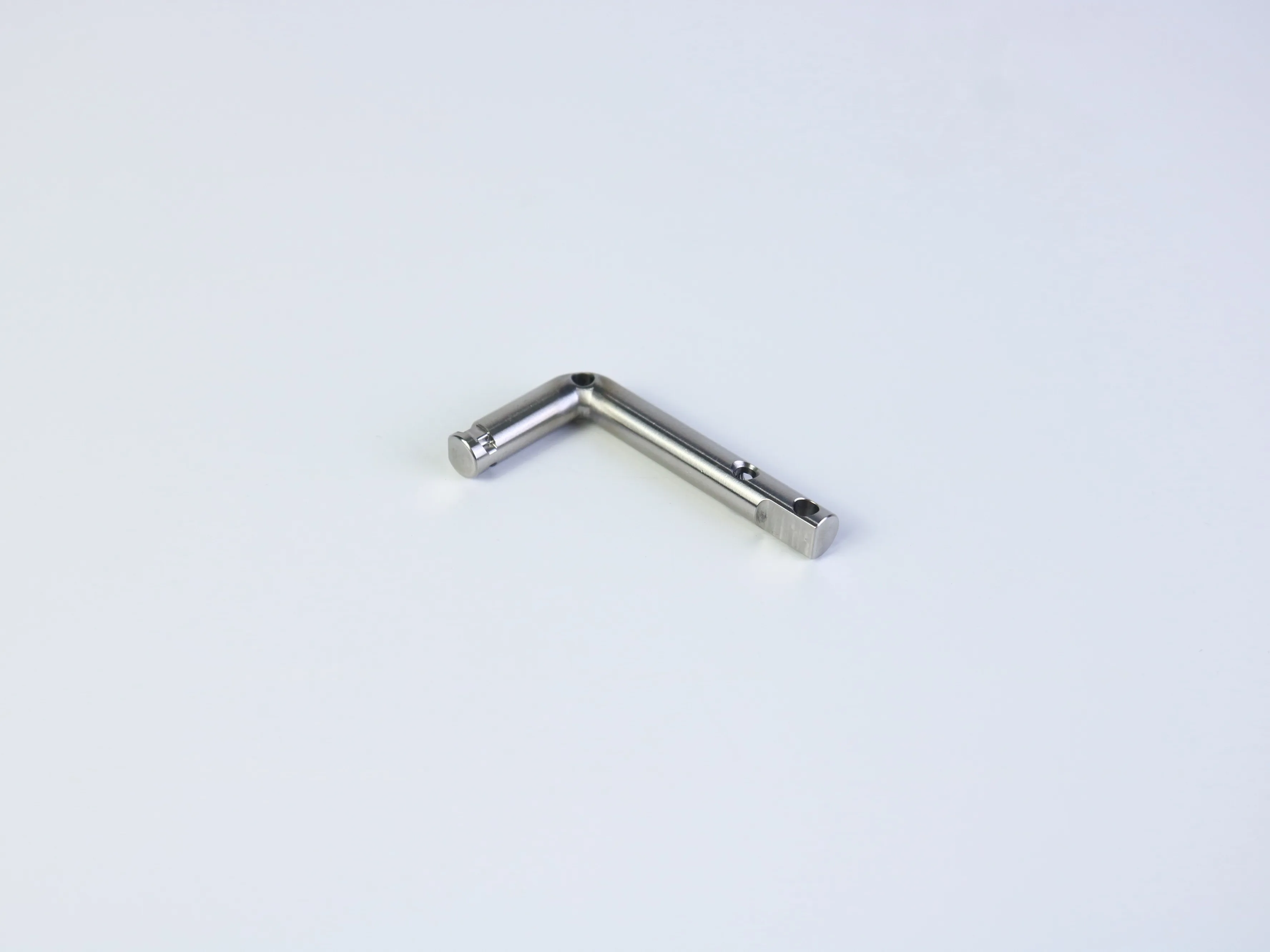
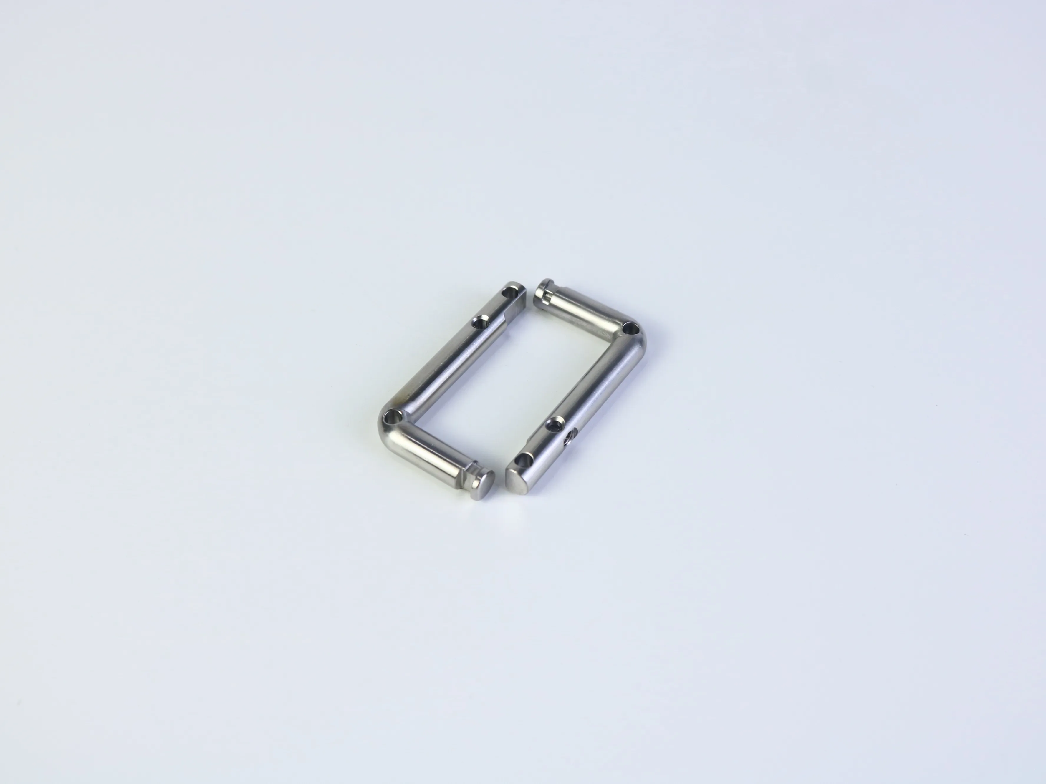
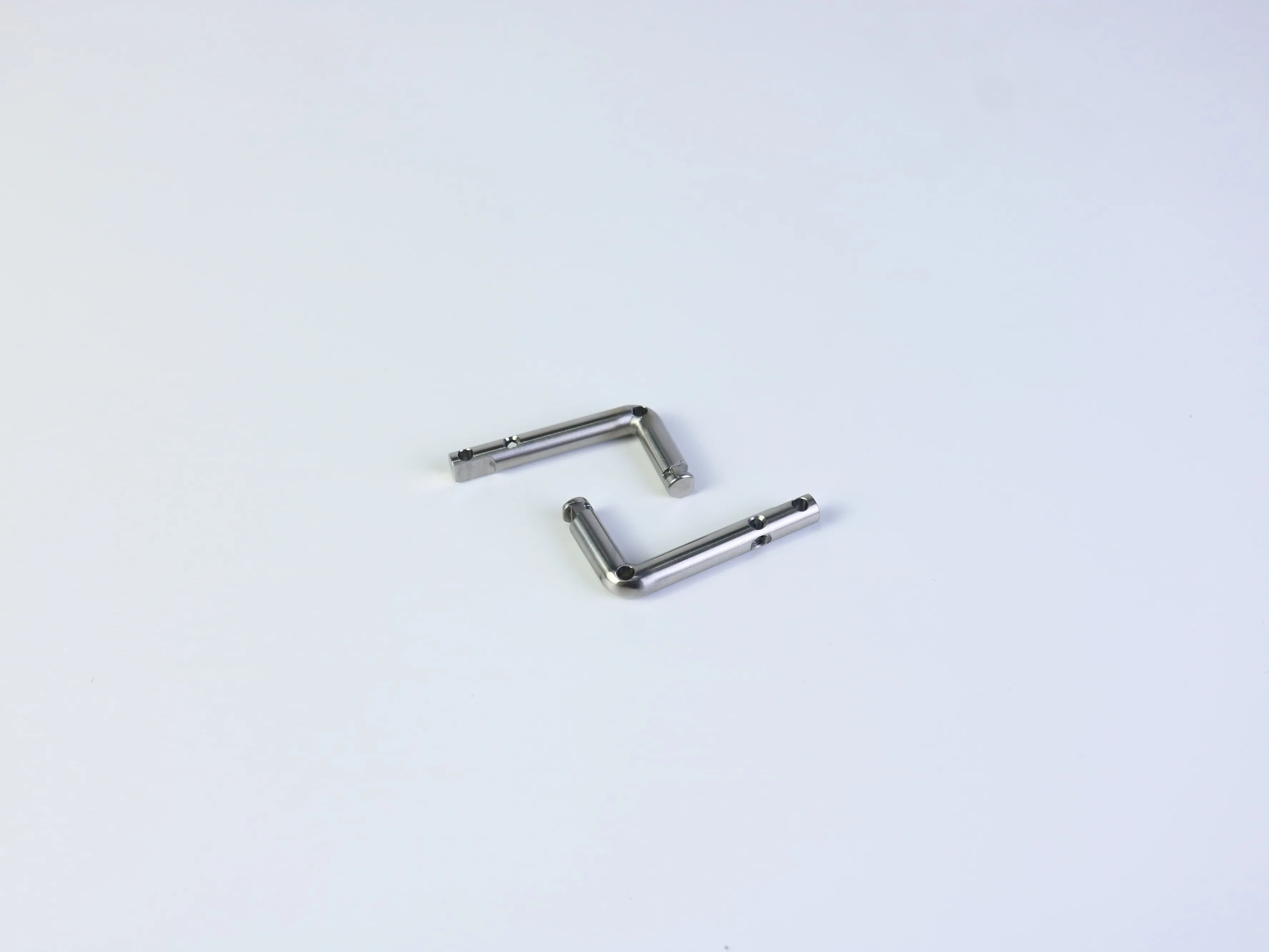
The photographed part combines several manufacturing operations in one compact structure. Its visible form suggests joined cylindrical sections, drilled openings, bent or angled geometry, and milled end features. That combination creates a key production challenge: every operation must preserve the position of the next locating surface. A small shift during cutting, welding, or fixturing can affect hole alignment, assembly clearance, and the final working movement.
A Typical Fabrication and Machining Sequence
For a component of this type, production normally starts with 304 stainless steel stock selected to match the drawing and service environment. The material is cut to controlled lengths, then formed or positioned before welding. Welding joins the sections, but it also introduces heat and possible distortion. For that reason, the part should be supported in a repeatable fixture and allowed to stabilize before critical machining.
After welding, CNC milling and drilling can establish the functional features. The holes visible in the photographs may serve as pivots, fastener locations, or alignment points; their exact purpose must be confirmed from the engineering drawing. Milling can also create flattened ends, steps, reliefs, or mating faces that cannot be produced accurately by cutting alone. Final deburring and cleaning are important because sharp edges, weld residue, or abrasive particles can interfere with assembly.
What Engineers Should Define Before Production
A manufacturable request should identify the material grade, stock condition, weld locations, finished dimensions, hole sizes, positional requirements, edge treatment, surface expectations, and inspection method. If the component is part of a moving assembly, include the mating parts or critical reference datums. The supplier can then build a fixture and inspection plan around the features that control function rather than judging appearance alone. The photographs show the general geometry, but they do not establish dimensions, tolerances, load capacity, weld standards, or surface finish.
Weld distortion control is especially important when a long arm meets a short angled section. Practical controls include consistent joint preparation, a stable fixture, a planned weld sequence, and inspection of the assembly datum before the final milling operation. Machining should reference surfaces that remain functionally relevant after welding, not simply the easiest visible edge. For repeat orders, record the fixture orientation, tool sequence, and inspection points so that the process is repeatable rather than dependent on operator adjustment.
A first-article review should separate visual acceptance from dimensional acceptance. Weld appearance, discoloration, burrs, and cleanliness can be reviewed visually, while hole diameter, center distance, angle, and mating-face position should be checked with suitable gauges or measuring equipment defined by the drawing. This distinction makes communication clearer and helps prevent a visually clean part from being approved before its assembly-critical features are verified.
Frequently Asked Questions
Is 304 stainless steel suitable for this type of part?
It can be suitable where corrosion resistance, cleanability, and general fabrication performance are required. Final selection depends on the environment, loads, temperature, and applicable specification.
Why machine the part after welding?
Post-weld machining can restore accurate hole locations, mating faces, and end geometry after heat-related movement. It also creates consistent interfaces for assembly.
What should be checked before shipment?
Check critical dimensions, hole size and position, overall alignment, weld appearance against the agreed requirement, burrs, cleanliness, and surface condition. Use a documented inspection report when the part is assembly-critical.
Have a Similar Stainless Steel Component?
Share your drawing, reference sample, material requirement, and critical inspection points. A production review can then focus on the fabrication sequence, weld distortion risk, machining datum strategy, and final assembly fit.
Request a Technical Review
Post time: Oct-22-2026


