
AL6061 Black Anodized Turned Threaded Sleeve: An Engineering Analysis of Structure, Machining and Selection
Based on the product images, product file information and company knowledge materials, this article analyzes an AL6061 black anodized CNC turned threaded sleeve from an engineer’s perspective, covering structural logic, machining route, thread fit, surface treatment, tolerance control, quality inspection and DFM review priorities.
Scope and Technical Limitations
This is a hollow rotational component made from AL6061 aluminum alloy, CNC machined by turning and finished with black anodizing. Based on the product images, the part has a bore, external threads, multiple cylindrical steps, annular locating shoulders and circumferential grooves. It represents a typical structure combining threaded connection, axial positioning and lightweight load support. The actual thread standard, precision grade, dimensional range, coating thickness and final application must be defined by the 2D engineering drawing, 3D model and assembly requirements. Images can identify visible structural features, but cannot replace dimensional inspection or functional validation.
This article is intended for product development, supplier evaluation, prototyping and production launch. Dimensions, thread specifications, coating thicknesses, certifications and applications that have not been confirmed by the supplied materials must not be treated as final technical commitments.
Contents
1. Product Definition 2. Operating Principles 3. Material Analysis 4. Machining Process 5. Black Anodizing 6. Technical Parameters 7. Tolerances and Inspection 8. DFM Review 9. Supplier Capability 10. RFQ Requirements 11. FAQ 12. SEO Recommendations 13. Engineering Conclusion
1. Product Definition: What Is a Turned Threaded Sleeve?
A turned threaded sleeve is a precision component manufactured from bar stock or tube stock by CNC turning. The process can produce external diameters, end faces, bores, internal and external threads, steps, grooves and chamfers. The pictured part has a multi-step coaxial form with at least the following identifiable areas:
- Hollow body: Openings are visible at both ends, indicating a through bore or a segmented internal bore structure.
- Threaded connection areas: An external thread is visible at one end, while an internal thread or internal thread entry is visible at the other end.
- Multiple locating steps: Several cylindrical sections and shoulders with different diameters are arranged through the middle area for axial stops, location or mating with adjacent components.
- Annular grooves and recesses: These features may provide clearance, accommodate a seal, reduce contact area or create functional boundaries.
- Coaxial rotational geometry: The overall design is organized around a rotational axis, making CNC turning a suitable primary process.
Structurally, the component is closer to a custom threaded connector, adapter sleeve, locating sleeve or tubing/mechanism interface than to a standard fastener. Its final application cannot be determined from appearance alone and should be evaluated against the assembly drawing, loading direction, service media and mating components.
2. Operating Principles: How Do the Threads, Shoulders and Bore Work Together?
2.1 Threads Provide a Removable Connection
When an external thread engages with a matching internal thread, the connection can transmit axial clamping force and, within its design limits, tensile load, compressive load and assembly torque. If the component is repeatedly assembled and disassembled, thread form, effective engagement length, lead-in chamfer and end relief directly affect assembly smoothness and service life.
The images do not provide a thread callout. Therefore, it is not possible to confirm whether the thread is metric, inch-based, a pipe thread, a trapezoidal thread or another special thread. Pitch, flank angle, thread tolerance class and handedness are also unconfirmed. Before production, the drawing should define:
- Thread system and nominal diameter;
- Pitch or threads per inch;
- Internal/external thread fit and tolerance;
- Effective thread length;
- Lead-in chamfer, thread relief and incomplete-thread requirements;
- Whether ring gauges, plug gauges or go/no-go inspection is required.
2.2 Steps and Shoulders Provide Axial Location
The central steps and annular shoulders may act as assembly stops, limiting insertion depth or controlling the axial position of adjacent components. Unlike the thread, which primarily provides the connection, the shoulder generally provides the location. Consequently, the perpendicularity of the shoulder face to the datum axis, face flatness and coaxiality between multiple steps may be more important than non-functional outside dimensions.
If a shoulder also serves as a sealing compression face or a bearing/bushing locating surface, its critical dimensions and geometric tolerances should be called out separately on the drawing rather than relying only on general tolerances.
2.3 The Bore May Support Weight Reduction, Flow or Mating
A hollow structure can reduce material consumption and component weight. It may also provide a passage for cables, fluids, rods or other internal elements. If the bore forms a sliding, clearance or threaded fit with another component, bore diameter, roundness, straightness, surface roughness and entry chamfer should be included in the inspection plan.
The images show only the openings and part of the internal wall. They cannot confirm the full internal geometry, whether the bore is stepped or whether an internal thread or blind-hole feature exists. Internal dimensions must therefore be defined by the engineering drawing.
3. Material Analysis: Why Is AL6061 Commonly Used?
The product file name identifies AL6061, and the images and file information also identify a black oxidation finish. AL6061 is commonly selected when a component needs a balance of low weight, machinability, general corrosion resistance and consistent appearance. For this type of turned sleeve, its engineering value includes:
- Weight reduction: Compared with steel, aluminum alloy can reduce the mass of rotating components, moving assemblies and portable equipment.
- Good turning suitability: It is suitable for external diameters, bores, steps, annular grooves and threads.
- Anodizing compatibility: Its surface can form a protective oxide layer and support black or other specified appearance finishes.
- Resistance in general environments: It can suit common industrial environments, but actual corrosion performance depends on alloy condition, surface treatment, film thickness and service media.
- Strength and cost balance: It can be suitable for many structural and interface components that are not exposed to extreme loading.
Material Temper Must Be Confirmed on the Drawing
“AL6061” identifies the alloy family but is not a complete material specification. The engineering drawing should also define the temper, such as T6 or another required condition, the applicable material standard and material certification requirements. If the component is exposed to sustained load, cyclic load, elevated temperature or corrosive media, material selection should not be based only on the image and alloy name.
For high-strength, fatigue-critical or aerospace applications, AL6061 should be compared with other aluminum alloys under the actual service conditions, including evaluation of strength, thread stripping, fatigue and corrosion.
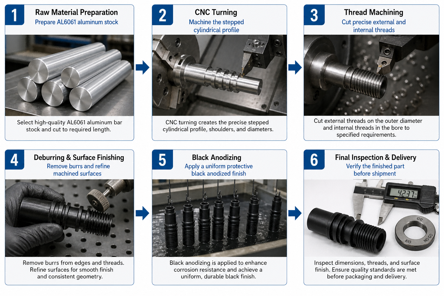
4. Machining Process: A CNC Turning-Based Route
The main features of this component are distributed around a central axis, so CNC turning or mill-turn machining should be evaluated first. A typical process route is:
- Material confirmation: Verify the AL6061 alloy, temper, batch and material certification.
- Blank preparation: Select bar or tube stock according to maximum outside diameter, overall length, bore allowance and clamping method.
- First setup: Machine the end face, outside diameters, external thread, steps, grooves and part of the bore.
- Reverse setup: Machine the opposite end face, bore, internal thread and reverse-side external features.
- Critical dimension reinspection: Focus on threads, bore, shoulder locations, overall length, outside diameters and coaxial relationships.
- Deburring and cleaning: Remove burrs at thread entries, bore intersections and groove edges so chips do not affect assembly.
- Pre-finish inspection: Confirm the dimensions are suitable before anodizing and define masking for mating surfaces that require protection.
- Black anodizing: Apply the specified color, process type, film thickness and appearance grade.
- Post-finish inspection: Check color uniformity, film integrity, thread go/no-go condition, critical mating dimensions and appearance.
- Packaging and protection: Isolate the anodized surfaces and threads to prevent scratches and impact damage during transport.
4.1 Setup Strategy Affects Coaxiality
If features at both ends cannot be completed in one setup, reverse clamping introduces datum-transfer error. For parts with functional relationships between internal and external threads, multiple steps and bore axes, the following should be considered:
- Use soft jaws or dedicated fixtures to protect machined surfaces;
- Use the finished bore or outside diameter as a secondary locating datum;
- Evaluate mill-turn machining to reduce the number of setups;
- Include critical coaxiality, runout and end-face locations in in-process inspection rather than relying only on final sampling.
4.2 Select the Threading Method by Specification
Internal and external threads may be produced by single-point turning, tapping, die threading or other dedicated tools. The choice depends on diameter, pitch, material condition, production volume and precision requirements. CNC thread turning provides better control for custom threads. Tapping may be more efficient for standard internal threads, but pilot-hole size, chip evacuation and tap-breakage risk must be evaluated.
The visual appearance of the threads cannot prove compliance with a particular standard. Formal quotation and production should be based on the thread callout and verification with the mating component.
5. Black Anodizing: Dimensional Engineering Beyond Appearance
Anodizing is not simply a process of “coloring aluminum black.” It forms an oxide layer on the aluminum surface and then achieves protective or decorative performance according to the specified process. For this component, black anodizing may provide:
- Improved surface wear and corrosion performance;
- More consistent appearance and product identification;
- Reduced direct exposure of the aluminum substrate;
- A specified black appearance for equipment, fixtures or consumer products.
5.1 Risks to Threads and Mating Dimensions
The anodizing film changes the surface dimension. On non-mating external surfaces with generous clearance, the main effects may be appearance and roughness. On internal and external threads, precision bores, sliding fits and locating shoulders, however, the film may cause:
- Tight thread engagement or failure to pass;
- Reduced effective bore size;
- Insufficient mating clearance;
- Non-uniform color and film thickness at sharp edges, groove bottoms and deep bores;
- Visible differences between masked and unmasked areas.
The drawing should therefore state whether dimensions apply before or after anodizing. During process review, define which areas require masking, allowance or secondary correction. Whether the threads are anodized, and whether they must maintain electrical conductivity or grounding, should also be decided in advance.
5.2 Surface Treatment Parameters to Confirm
The available materials confirm only the direction of black anodizing and do not confirm a specific process. Before publication or production, define:
- Anodizing type: decorative/protective or hard anodizing;
- Film thickness range;
- Black color standard or approved sample;
- Appearance grade, color difference and allowable defects;
- Whether threads, bores and end faces are masked;
- Whether sealing is required;
- Whether wear, corrosion or specific environmental testing is required.
“Black anodized” alone does not establish a specific film thickness, hardness or military/industry standard unless those requirements are explicitly defined on the drawing or purchase order.
6. Recommended Technical Parameter Table
The table separates information identifiable from the images or supplied materials from information that must be confirmed by engineering documentation.
| Parameter | Currently Identifiable | To Confirm Before Release |
|---|---|---|
| Part type | Custom CNC turned hollow threaded sleeve / adapter-type component | Final product name and application description |
| Primary process | CNC turning; mill-turn may be considered where necessary | Specific machine, tooling and setup strategy |
| Material | AL6061 | Temper, material standard and batch certification |
| Surface finish | Black anodizing | Anodizing type, film thickness, color standard and sealing |
| Visible features | Bore, external thread, internal thread/thread entry, multiple steps and annular grooves | Dimensions, locations and functional datums for each feature |
| Thread data | Threads are visible, but the specification is not supplied | System, diameter, pitch, tolerance class, effective length and handedness |
| Size range | A small rotational component; the ruler image is for visual reference only | Overall length, maximum outside diameter, bore and allowable ranges |
| Tolerance capability | Company information states standard machining tolerance of ±0.01 mm and up to ±0.005 mm for special areas | Actual tolerance, inspection datum and applicable features for this part |
| Surface roughness | Company information states an Ra capability of 0.1–3.2 | Specific Ra requirements for each machined surface |
| Quality documents | Material certificates, inspection records and first-article/full-dimensional reports may be supplied by project | Document list, sampling ratio and third-party inspection requirements |
| Packaging | Separated, anti-scratch packaging suitable for international transport can be provided | Individual protection, thread protection, labels and batch traceability |
7. Tolerances and Inspection: Do Not Treat ±0.01 mm as the Default for Every Feature
The company information states a standard machining tolerance of ±0.01 mm and up to ±0.005 mm for special precision areas. It also states that actual capability depends on material, geometry, size and feature requirements. These values should therefore be understood as capability information, not as an automatic tolerance commitment for every dimension of this part.
7.1 Features Recommended for Control
- Effective thread diameter and profile: Verify with suitable ring gauges, plug gauges, the three-wire method or another approved method.
- Bore size and roundness: Select an internal micrometer, air gauge or other suitable instrument according to the bore size.
- Outside diameters and steps: Check critical mating diameters and the dimensional chain between steps.
- Axial shoulder location: Confirm the distance from the stop face to the datum end face.
- Coaxiality and radial runout: Inspect the relationship between bore, outside diameters, thread axis and steps against the defined datum scheme.
- Overall length and end-face condition: Prevent changes in end faces or chamfers from affecting assembly depth.
- Post-anodizing fit: At minimum, validate the functional assembly of critical threads and mating bores.
7.2 Recommended Inspection Documents
For prototypes or first articles, request a critical-dimension report, thread inspection record, material certificate and surface-treatment certificate. For production, define first-article inspection, in-process sampling and outgoing inspection according to risk and volume. For medical, automotive, aerospace or other regulated applications, confirm the required quality documents, traceability depth and customer-specific requirements at the order stage.
The company information identifies six QA/QC inspectors and measurement resources including CMM and two-dimensional measuring equipment, together with incoming, first-article, in-process and pre-shipment inspection. The exact gauges and report format for this component should still be confirmed during engineering review.
8. DFM Review Priorities: How to Reduce Machining and Assembly Risk
8.1 Avoid Tight Tolerances Without a Functional Purpose
Thread fits, locating shoulders, critical bores and sealing surfaces may require tighter tolerances. Non-functional outside diameters, decorative steps and groove bottoms that do not participate in assembly should not automatically receive ultra-tight tolerances. Applying ±0.005 mm unnecessarily increases machining time, inspection cost and scrap risk without necessarily improving assembly performance.
8.2 Provide Complete Conditions for Threading
The end of a thread should include a relief groove or sufficient clearance so the tool can exit completely without producing incomplete threads. The thread entry should have a suitable chamfer to prevent cross-threading during assembly. For blind-hole internal threads, define effective thread depth, pilot-hole depth and the allowable incomplete thread at the bottom.
8.3 Control Thin Walls and Length-to-Diameter Ratio
A hollow aluminum component with a small wall thickness or long length may experience deformation, ovality or appearance variation during clamping, cutting and anodizing. Drawing review should consider minimum wall thickness, clamping locations, machining allowance and dimensional stability after heat or surface treatment.
8.4 Define Chamfers, Radii and Groove-Bottom Requirements
Sharp internal corners increase tool wear and machining difficulty; small radii are generally more compatible with turning-tool geometry. If a groove bottom has no functional purpose, avoid an excessively small radius or narrow groove width. For a sealing groove, define width, depth, radius and surface roughness from the seal specification rather than drawing it only for visual effect.
8.5 Include Anodizing in the Early Dimensional Chain
If the threads or bore must maintain assembly function after anodizing, identify the pre- and post-treatment datums and critical dimensions on the drawing. A practical validation route is to first produce an unanodized sample for mechanical assembly, then an anodized sample for color, film and thread-fit validation, and finally release the confirmed process window for production.
9. Supplier Manufacturing and Quality Capability Reference
According to the supplied company knowledge materials, Shenzhen Perfect Precision Products Co., Ltd. is an OEM/ODM custom manufacturer. The materials describe capabilities including CNC turning, CNC milling, mill-turn machining, injection molding, sheet metal fabrication, casting, forging, rapid prototyping and surface-treatment coordination. The listed service sectors include medical, aerospace, automotive, marine, robotics and automation, agricultural machinery, industrial equipment and electronics.
Capabilities most directly related to this component include:
- Turning outside diameters, bores, steps, grooves and threads;
- Using mill-turn machining to reduce repeated setups for complex components;
- Performing material, first-article, in-process and outgoing inspection;
- Providing material certificates, inspection records and first-article reports according to project requirements;
- Coordinating black anodizing and other surface treatments;
- Supporting staged introduction from prototype to pilot production and volume production.
The supplied materials identify ISO9001:2015 and ISO13485:2016 as verified quality management systems. Other certifications listed on external materials, including ISO14001, ISO45001, AS9100 and IATF16949, were marked in the knowledge materials for further verification. A product page should not present certifications without original supporting certificates as confirmed. For industry-specific orders, verify certificate scope, validity and applicable manufacturing site during the contract or supplier-audit stage.
10. What Information Should Be Submitted for an Engineering RFQ?
To obtain an actionable quotation and reliable lead time, submit the following information whenever available:
- 2D engineering drawing and 3D model, preferably in a common format such as STEP or IGES;
- AL6061 material condition and certification requirements;
- Internal and external thread standards, pitch, tolerance and mating-part information;
- Critical dimensions, tolerances, geometric tolerances and surface roughness;
- Black anodizing type, film thickness, color and masking areas;
- Prototype quantity, pilot quantity, monthly demand or annual forecast;
- Inspection reports, material certificates, RoHS/REACH or other compliance documents;
- Packaging, marking, batch traceability and transportation requirements;
- Actual service conditions, including load, speed, temperature, humidity, media and assembly frequency.
If no drawing is available yet, photos, a physical sample or a dimensioned sketch can support a preliminary manufacturability review. However, a preliminary quotation must clearly state its assumptions. Final price, tolerances, finish, lead time and inspection documents should be fixed only after drawing or sample measurement review.
11. Frequently Asked Questions
Q1: Is this component aluminum alloy or steel?
The product file name identifies AL6061, and the images show a black surface treatment. The current analysis can therefore use AL6061 aluminum alloy with black anodizing as the working direction. Temper and material certification must still be confirmed in the order documents.
Q2: Does black anodizing mean hard anodizing?
No. Black describes the color only. It does not establish the anodizing type, film thickness or wear grade. The treatment type and film thickness should be defined on the engineering drawing.
Q3: Can the images confirm the thread specification?
No. The images show that threaded features exist and indicate their approximate locations, but they cannot reliably confirm nominal diameter, pitch, thread form, tolerance class or thread standard. These details must be confirmed from the drawing or physical measurement.
Q4: Is this type of part suitable for CNC turning?
Yes. Its main features are arranged around a central axis, so turning can efficiently produce the outside diameters, end faces, bore, steps, grooves and threads. Mill-turn machining can be evaluated when both ends are complex or setup reduction is important.
Q5: Does the company’s ±0.01 mm capability apply to every dimension?
It should not be interpreted that way. ±0.01 mm is a standard machining capability stated in the supplied company information. Actual achievable precision depends on material, size, geometry, datum, volume and inspection method. The specific tolerances for this component must follow the drawing.
Q6: Can the threads still assemble correctly after anodizing?
Yes, if the process is designed accordingly, but the effect of the film on thread form and effective dimensions must be considered in advance. Define whether the threads are masked, establish dimensional allowance and post-anodizing go/no-go inspection, and use the mating component to verify assembly torque and effective engagement length.
Q7: Do the bore and threads need surface treatment?
Not necessarily. The decision depends on corrosion protection, appearance, conductivity, wear and assembly requirements. The bore, threads or contact surfaces may require local masking, but the final solution must be defined through drawing and process review.
Q8: Can the part be quoted without a drawing?
A budgetary estimate can be prepared from photos, a sample or a sketch, but its assumptions must be stated and it cannot replace a formal engineering quotation. A drawing or measured sample is still required to lock dimensions, tolerances, finish, lead time and inspection documents.
Q9: Which industries may use this type of part?
Structurally, it may suit equipment and mechanisms requiring a lightweight threaded connection, axial location or hollow passage. The specific industry cannot be determined from the images alone. Application suitability should be evaluated against load, media, temperature, cleanliness and regulatory requirements.
Q10: What is the most important validation before mass production?
At minimum, validate mechanical assembly, thread go/no-go and torque, critical dimensions and coaxiality, and anodized color and fit. For regulated applications, also confirm material traceability and quality documentation.
12. Product Page and SEO Recommendations
Recommended H1
AL6061 Black Anodized CNC Turned Threaded Sleeve with Internal and External Threads
Recommended Internal Link Topics
- CNC Turning vs. CNC Milling: How to Select the Process by Part Geometry
- AL6061 vs. AL7075: Strength, Machinability and Anodizing Considerations
- How Anodizing Affects Aluminum Threads and Mating Dimensions
- DFM Review Checklist for CNC Turned Parts
- What Should Be Included in a First-Article Inspection Report?
Recommended External Reference Direction
When the page is formally published, add the applicable aluminum alloy, anodizing, thread, geometric dimensioning and tolerancing, and customer-specific RoHS/REACH references according to the actual materials and processes used. Verify the edition, scope and supplier certificates before citing any standard. Listing a standard name without connecting it to a process or inspection requirement should be avoided.
13. Engineering Conclusion
The images and supplied materials support the conclusion that this is a custom rotational component made from AL6061, primarily processed by CNC turning, incorporating a bore, threads, steps and annular grooves, and finished with black anodizing. The main manufacturing challenge is not simply turning the external profile. It is controlling the coaxial relationship between multiple datums, maintaining assembly performance of internal and external threads, controlling dimensional consistency after reverse clamping, and accounting for the effect of anodizing on threads and mating surfaces.
The most reliable engineering path is to confirm threads, dimensions, tolerances and surface-treatment requirements through the 2D/3D drawing; conduct a DFM review and validate an unanodized sample; then validate fit and appearance on an anodized sample; and finally release production based on first-article inspection, material traceability and surface-treatment records. Avoid assigning unnecessarily tight tolerances to dimensions without a defined function. Features responsible for connection, location or sealing should have separately defined datums, geometric tolerances and inspection methods.
Post time: Oct-22-2026


