
Engineering & Procurement Guide
Design and RFQ Checklist for CNC Machined Metallic Domed Cap Nuts
A photograph can reveal the general shape of a domed cap nut, but it cannot replace a controlled drawing. This practical guide explains how engineers and buyers can define the thread, dome, hex feature, material, inspection requirements, and quotation package before requesting custom machining.
Start with a neutral component description
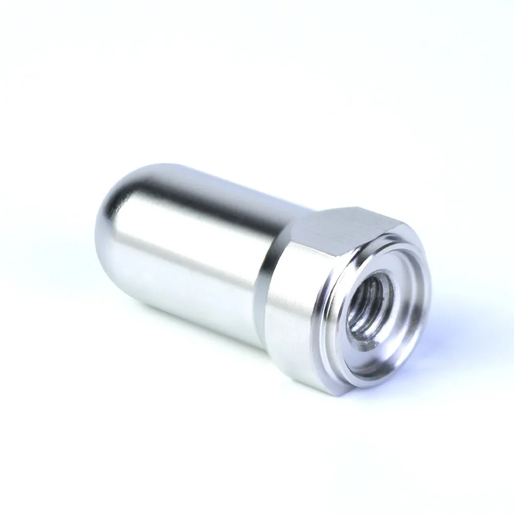
A suitable preliminary description is metallic domed cap nut, closed-end cap nut, or acorn-style cap nut. These terms describe the visible form without assigning a material, standard, or performance level. In an RFQ, that distinction matters because similar-looking cap nuts can be made as one-piece machined parts, two-piece assemblies, formed components, or other constructions.
The RC Fastener reference separates one-piece and two-piece closed-end hex cap nuts and describes common purposes such as covering exposed threads and providing a finished appearance. That information helps establish vocabulary, but it does not prove the construction of the pictured component. The buyer should state the required construction on the drawing or ask the supplier to propose an approved manufacturing route.
Record only what can be seen: the approximate external form, the presence of a rounded end, the hexagonal feature, and any visible internal-threading indication. Do not infer the thread standard, internal depth, material grade, corrosion performance, load rating, or end use from a product image.
Define the open end and internal thread
The open end is usually the most important functional area to define. Is the cavity internally threaded? Is the thread continuous or partial? Is the cavity blind, or does it pass through the component? Does the internal end include a drill point, relief, chamfer, or another termination? A close-up photograph may suggest threading, but it cannot establish the thread designation or effective thread length.
A complete RFQ should identify the thread system and designation, such as the selected metric or inch system, nominal size, pitch or threads per inch, tolerance class, and required fit. These values must come from the buyer’s joint design or controlled drawing. They should not be copied from a catalogue table merely because the outside profile looks similar.
Specify effective thread depth separately from total cavity depth. The usable thread length may be shorter than the drilled cavity, and the internal end condition may affect whether the mating bolt or stud can enter safely. If the component is intended to cover exposed threads rather than carry a defined joint load, state that function and define the maximum allowable interference.
Check blind-hole depth against fastener protrusion
For a blind threaded cap nut, the mating fastener’s protrusion is a design input. The assembly needs sufficient effective thread engagement, but the bolt or stud must not bottom out against the cavity end or the internal surface beneath the dome. This is a fit and function review, not an appearance decision.
Before sending the RFQ, compare:
- mating fastener length and maximum expected protrusion;
- effective internal thread length;
- total drilled cavity depth;
- drill-point geometry or internal end relief;
- wall thickness around the cavity and beneath the dome; and
- washers, spacers, joint compression, or other assembly stack-up.
There is no universal safe depth that can be assigned from a photograph. The correct values depend on the selected thread, joint design, material, manufacturing process, and acceptance criteria. Put the functional clearance requirement on the drawing and ask the supplier to identify any assumptions before quoting.
Define the hexagonal wrench feature and tool access
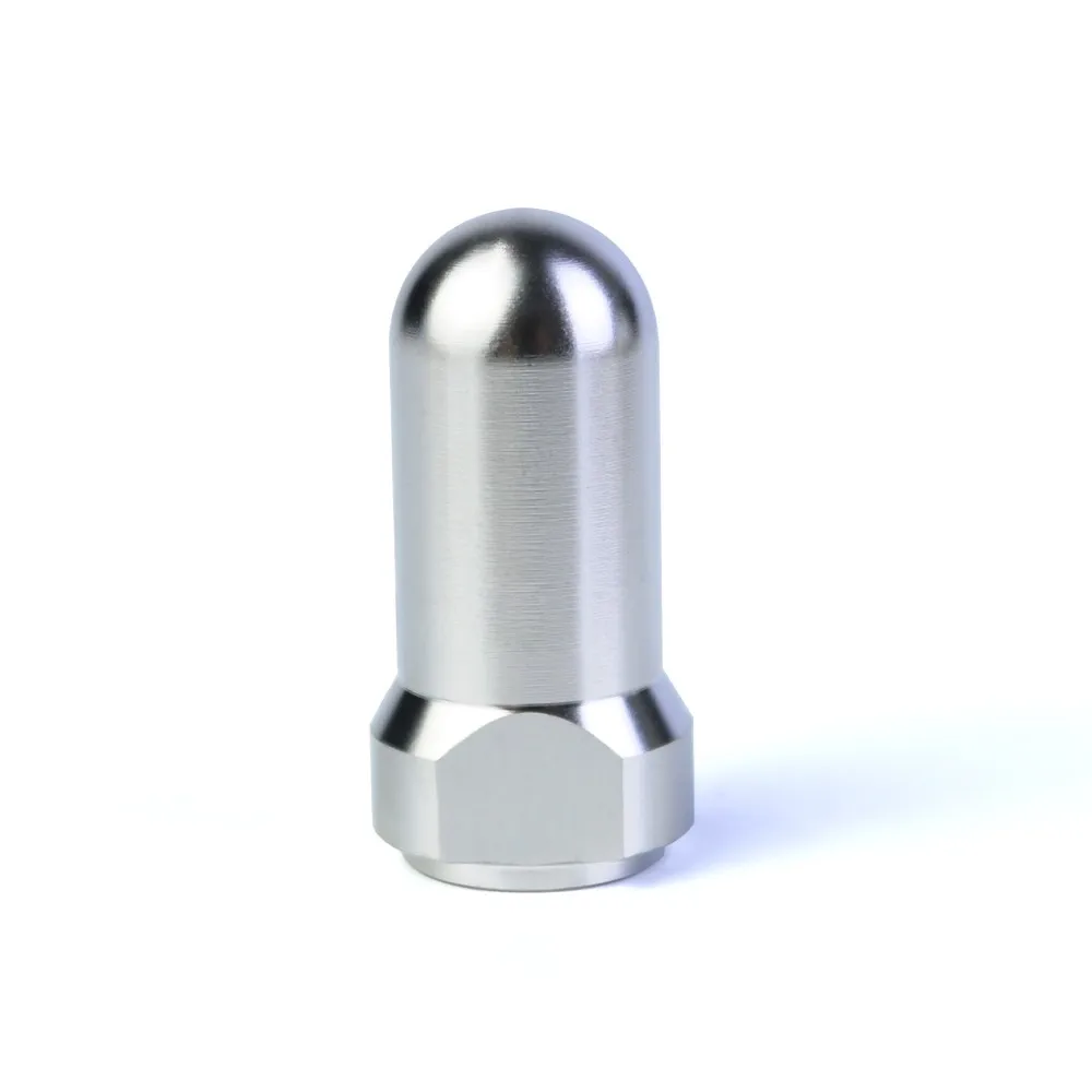
The hexagonal area should be specified using a clear measurement convention, such as across-flats, together with the hex height, corner treatment, transition to the cylindrical wall, and available wrench zone. The drawing should also state whether the hex is intended for installation torque, anti-rotation, hand tightening, or visual appearance only.
Wrench clearance is a system requirement, not merely a dimension on the nut. Review radial space, nearby shoulders, recessed locations, socket access, open-end wrench access, and the possibility of contact with a neighboring component. A supplier cannot determine the correct machining sequence or assembly access from a photograph alone.
The ITP Bolt reference lists useful catalogue fields for a metric domed cap nut, including nominal size and thread pitch, across flats, overall height, drill depth, and hexagon height. These fields are good examples for an RFQ checklist. They are not dimensions for the supplied images and must not be copied into a purchase order without confirmation.
Protect the dome and define internal clearance
The dome is both a visible feature and an internal-space constraint. Define the outside profile, overall height, crown radius or profile method, and transition from the hexagonal base to the cylindrical section. If appearance is important, separate visual requirements from dimensional requirements. If the dome protects a protruding fastener, define the maximum protrusion and the required internal clearance.
Review wall thickness, tool access, residual tool marks, blend lines, dents, polishing direction, and the possibility of a drill point approaching the crown. The rounded outer surface does not prove a uniform wall thickness or a particular forming method. Even an internal surface that is not visible in service needs enough definition to prevent interference and support inspection.
Specify material and surface condition separately
“Metallic” is a visual observation, not a material specification. The buyer should identify the material grade, applicable material standard, heat-treatment condition when relevant, and required documentation. The PFTWORLD customized CNC machining page lists stainless steel among its materials, but that page statement does not prove that the pictured component is stainless steel or that it uses a particular grade.
World Stainless provides general educational background on the naturally occurring passive layer associated with stainless steels. That background cannot identify the material in an image and cannot establish a corrosion rating for this component. If corrosion performance matters, specify the exact grade, environment, surface condition, and documentation requirement in the purchase package.
Surface condition is a separate field. State whether the required condition is as-machined, deburred, polished, passivated, plated, coated, or another approved finish. Identify protected surfaces, treatment coverage, dimensional allowances, and any post-treatment inspection. A finish name must not be used as a substitute for a material grade.
Make inspection measurable
An RFQ should identify what will be inspected and how the result will be accepted. Depending on function, the inspection plan may include thread size and fit, effective thread depth, total cavity depth, across-flats dimension, hex height, overall height, dome profile, concentricity or runout, burrs, sharp edges, surface condition, and visible defects.
Separate critical characteristics from informational checks. Thread gauging may be needed for assembly fit, while the dome may require a drawing-defined contour or a specified measurement method. If a tolerance is important, place it on the drawing instead of relying on a generic tolerance assumption. If material certificates, first-article records, sample approval, or traceability are required, list them explicitly.
Avoid promising a tolerance, load, torque, corrosion rating, certification, or inspection result before the buyer and supplier agree on the drawing and acceptance criteria. “Precision” becomes meaningful only when it is connected to a measurable requirement.
Build a comparable sample and production RFQ package
A practical RFQ package should contain the latest controlled drawing, a three-dimensional model when useful, required quantity or forecast, packaging expectations, inspection requirements, and revision level. The drawing should identify the thread, material, surface condition, key dimensions, tolerances, datum scheme, edge treatment, and functional notes.
For sample work, state whether the sample is intended for dimensional approval, assembly testing, visual approval, process review, or a combination. Define what changes require re-approval. For production, state the lot definition, sampling or inspection level if already selected, traceability needs, and the treatment of nonconforming parts.
Once these requirements are clear, a supplier discussion can focus on suitable CNC turning, drilling, milling, deburring, and inspection steps. PFTWORLD’s customized CNC machining page describes customized CNC turning, drilling, milling, and related services and lists stainless steel among its materials. Its mechanical-solutions page also includes CNC lathe and turning content. These are statements on the respective pages, not independent validation of this specific component, material, capacity, tolerance, certification, or lead time.
RFQ checklist before you request a quotation
- Controlled drawing, revision, and 3D model where needed
- One-piece, two-piece, or other construction requirement
- Thread system, size, pitch or TPI, fit, and tolerance class
- Effective thread depth, total cavity depth, and fastener protrusion
- Across-flats dimension, hex height, and wrench clearance
- Dome profile, internal clearance, edge treatment, and appearance
- Material grade, documentation, surface condition, and post-treatment inspection
- Sample purpose, first-article requirements, production inspection, packaging, and traceability
Questions to resolve with the machining supplier
A quotation becomes easier to compare when the supplier is asked to separate confirmed requirements from manufacturing assumptions. Request a short review of the proposed setup, workholding approach, tool access, internal-thread process, deburring method, and inspection sequence. The goal is not to force a specific process, but to make sure the proposed process can produce the controlled features without introducing avoidable marks or access problems.
Ask which characteristics the supplier considers critical, how the thread will be verified, and how the internal cavity will be inspected when direct access is limited. If the dome profile or appearance is important, agree on a visual sample, contour reference, or measurement method before production. If the part will be assembled with a mating bolt, provide the mating hardware or its verified specification so protrusion and fit can be reviewed against the actual joint.
Finally, ask the supplier to list exclusions: unprovided material documents, undefined surface treatment, missing tolerances, unconfirmed quantity, or packaging assumptions. A clear list of open items prevents a low-detail image from becoming an inaccurate purchase specification.
Conclusion: quote the definition, not the resemblance
A domed cap nut may look simple, but a reliable quotation depends on several decisions: construction, thread system, effective depth, fastener protrusion, wrench access, dome clearance, material, surface condition, and inspection method. The photograph is useful for starting the conversation. The controlled drawing is the authority for quoting and acceptance.
Before requesting a quotation, confirm every field that affects fit, function, appearance, and acceptance. Ask the supplier to identify assumptions and open questions instead of filling missing data with a standard part number. For a drawing-based review of a custom component, contact PFTWORLD through the verified inquiry route.
Need a drawing-based machining review?
Share your controlled drawing, thread requirements, material, surface condition, quantity, and inspection expectations so the quotation discussion can focus on the actual part definition.
Editorial note: This article uses the supplied images as visual references only. Material grade, dimensions, tolerances, standards, certifications, end use, and manufacturing capability must be confirmed through controlled technical documents and supplier review.
Related service information: Customized CNC Machining Parts and CNC Engineered Solutions.
Post time: Nov-05-2026


