
Custom Compound Spur Gears Manufactured to Your Drawing

Custom Gear Manufacturing
Custom Compound Spur Gears Manufactured to Your Drawing
Drawing-based OEM gear manufacturing for compound spur gears, double spur gears and custom metal transmission components. Shenzhen Perfect Precision Products Co., Ltd. reviews your gear geometry, material, quantity and inspection requirements before quotation.
Custom Gear Manufacturing for Fit-Critical Assemblies
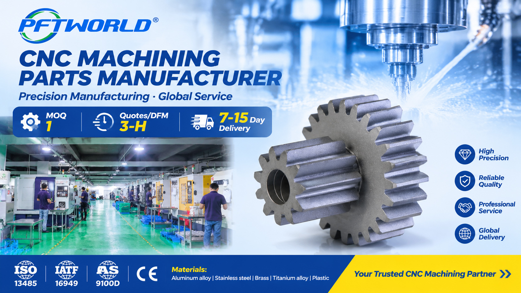
A compound spur gear combines two straight-tooth gear sections on a common axis. The reference geometry for this page shows a larger external gear, a smaller external gear, a visible central bore and an integrated hub or shoulder region. This form may be considered for compact motion-transmission or equipment mechanisms, but the final function must be confirmed from the mating gear, operating load, speed and approved engineering drawing.
Shenzhen Perfect Precision Products Co., Ltd. provides drawing-based OEM and ODM manufacturing for gears and other precision components. The documented factory service range includes CNC milling, CNC turning, mill-turn machining, gear production, surface-finishing coordination and dimensional inspection. The exact process route for each gear is selected after an engineering and manufacturability review rather than assumed from a photograph.
Why a Drawing Review Matters
A gear can appear visually correct and still fail in assembly or service when the functional parameters are not controlled. Before quotation, the engineering team should review the following points:
- Tooth count, module or diametral pitch, pressure angle, tooth profile and face width determine whether the gear can mesh with its mating component.
- Bore diameter, keyway, spline or other drive features must match the shaft and maintain the required fit and concentricity.
- Material grade, hardness, heat treatment and surface finish should match the intended load, speed, wear and environment.
- Deburring and edge control should protect handling and assembly without changing the functional tooth profile.
- Prototype and repeat-production requirements should be aligned early so inspection and process controls remain consistent between batches.
Visible Product Characteristics
The pictured component appears to be a custom compound spur gear, also described as a double spur gear when two straight-tooth sections are integrated on one part. Visible characteristics include a larger gear section, a smaller gear section on the same axis, a central bore, a raised hub or shoulder, machined circular faces and visible tooth flanks.
The photograph does not confirm the material, dimensions, gear standard, heat treatment, accuracy grade, operating load or application. These details must be taken from the latest 2D drawing, 3D CAD model, dimensioned sketch or approved physical sample. No exact size or gear parameter should be inferred from visual proportions.
For a new design, the drawing package should also identify the functional datum structure, mating components, inspection reference, expected service life and any acceptance criteria. For a replacement part, the buyer should provide the existing gear or measured sample together with the mating assembly information. This helps separate a visual match from a true functional replacement and reduces the risk of quoting an unsuitable geometry.
Project Specification Framework
| Item | Quotation Guidance |
|---|---|
| Part type | Compound spur gear or double spur gear; final terminology is subject to drawing review. |
| Gear parameters | Tooth count, module or diametral pitch, pressure angle, tooth profile, face width and gear standard must be confirmed. |
| Material and hardness | To be selected for load, speed, wear and environment. Aluminum, alloy steel, stainless steel, brass, bronze, copper and engineering plastics are listed machining materials. |
| Manufacturing route | CNC turning, milling, mill-turn, gear production or a combined route, selected after DFM review. |
| Factory-level capability | Standard machining capability is documented as ±0.01 mm; special areas may be reviewed to ±0.005 mm. Gear-specific requirements remain subject to drawing review. |
| Surface treatment | Anodizing, black oxide, powder coating, polishing and plating are available subject to material compatibility and project requirements. |
| Inspection | Incoming, first-article, in-process or sampling, and pre-shipment inspection are documented. CMM and 2D measuring instruments are available. |
| Drawing formats | STEP, IGS, STL, X_T, PDF, DWG and DXF are listed as accepted engineering formats. |
Product-Specific Manufacturing Benefits
Controlled Tooth and Assembly Geometry
Tooth geometry, bore fit and hub dimensions work together. A drawing-based review helps identify critical datums, mating surfaces and inspection points before material is purchased or production is scheduled.
Process Selection for Stepped Coaxial Parts
The combined gear and hub geometry may require more than one operation. Depending on the design, turning, milling, mill-turn machining, gear production and secondary finishing can be coordinated into a controlled routing plan.
Material and Finish Coordination
The factory-level material range supports review of metals and engineering plastics. Surface treatment options can be considered after confirming the base material, wear requirements, corrosion environment, appearance and applicable finish standard.
Inspection Planning for Functional Features
Inspection planning may focus on the bore, critical diameters, face widths, concentricity-related features, tooth geometry and specified surface requirements. The documented resource includes six QA/QC inspectors and five testing instruments.
Prototype to Production Support
Prototype, pilot-run and production support are documented capabilities. Inspection scope, process stability, batch quantity and transition requirements should be agreed before repeat orders are released.
Manufacturing and Quality Workflow
- Drawing review: confirm gear type, tooth parameters, datums, bore or keyway, material, heat treatment, finish, quantity and inspection requirements.
- Material verification: match the selected grade and condition to the drawing and purchase requirements. Material certificates can be requested when applicable.
- Process planning: select CNC turning, milling, mill-turn, gear production or a combined route according to geometry, access, datum strategy and inspection needs.
- Machining and deburring: produce the gear and hub features, then control burrs and edge breaks without changing functional tooth surfaces.
- Surface treatment: coordinate the agreed finish, color, coating thickness or plating standard through the appropriate production route.
- Inspection: use the agreed dimensional checks and instruments, including CMM or 2D measurement where appropriate.
- Final release: confirm the inspection scope, documentation, packaging and shipping requirements before dispatch.
A clear workflow is especially useful when a gear moves from a first prototype to a repeat order. The approved revision, material batch information, critical inspection points and agreed finish should remain traceable throughout the project. If the buyer changes tooth geometry, bore fit, hardness or quantity, the quotation and inspection plan should be reviewed again rather than carried forward without engineering confirmation. This approach supports better communication between design, purchasing, production and quality teams.
Potential Industries and Applications
The exact application of the pictured component is not confirmed. Based on the visible gear form and the company’s documented industry coverage, the part may be evaluated for robotics and automation mechanisms, industrial equipment, agricultural machinery, automotive mechanisms, marine hardware and other motion-transmission assemblies.
These are potential application categories, not confirmed uses of this specific part. Please provide operating load, speed, duty cycle, lubrication, temperature, corrosion exposure and mating-gear information before approving the design, material or heat treatment.
For robotics and automation, the buyer may need to prioritize compact packaging, repeatable movement and assembly fit. For industrial or agricultural equipment, load cycles, contamination, impact and maintenance conditions may be more important. For automotive or marine mechanisms, material selection, corrosion resistance, traceability and project-specific validation should be defined in the drawing package. These considerations guide the review; they do not replace application testing or customer approval.
Information Required for an Accurate RFQ
Please include the following information when requesting a quotation:
- 2D drawing with gear parameters, datums, tolerances and inspection callouts.
- 3D CAD file, if available, together with the latest drawing revision.
- Material grade, temper, hardness and heat-treatment requirements.
- Tooth count, module or diametral pitch, pressure angle, gear standard and mating information.
- Bore, keyway, spline, hub and shaft details, including fit requirements.
- Prototype, pilot and repeat-production quantities.
- Surface finish, coating, plating, packaging and inspection-report requirements.
- Target delivery date and intended operating environment.
Why Work with Shenzhen Perfect Precision Products Co., Ltd.?
The supplied company documentation identifies Shenzhen Perfect Precision Products Co., Ltd. as a custom OEM/ODM manufacturer founded in 2012, with more than 100 professional staff and more than 79 machines across CNC machining and additional production processes. The company documents ISO9001:2015 and ISO13485:2016 as verified quality certifications. It also records six QA/QC inspectors, five testing instruments, CMM and 2D measuring resources, drawing review support and experience serving customers in more than 100 countries and regions.
For a gear buyer, this factory-level combination can reduce coordination between engineering, machining and inspection. CNC milling, CNC turning, mill-turn machining, gear production, finishing coordination and additional fabrication services can be reviewed through one quotation process. That does not remove the need for a controlled drawing; it makes the drawing review more useful because material, process, quality and logistics questions can be considered together.
For repeat-production programs, the same review can clarify whether the selected route remains suitable as quantity, finish, inspection documents or delivery planning changes. Buyers can identify which requirements are fixed and which are project-dependent before comparing quotations, helping avoid a low initial price that excludes necessary inspection, treatment or packaging steps.
These are company-level capabilities. They do not mean that the pictured gear already has a confirmed material, tolerance, inspection result or application approval. The project drawing and quotation remain the basis for the final manufacturing and quality requirements.
Frequently Asked Questions
Can you manufacture this gear from a photograph?
A photograph supports an initial discussion, but it does not provide enough information for an exact quotation. Send a drawing, CAD model, dimensioned sketch or physical sample with the required gear parameters.
What materials can be considered?
The documented machining range includes aluminum alloys, titanium alloys, stainless steel, alloy steel, brass, bronze, copper and engineering plastics. The final selection depends on load, speed, wear, environment, heat treatment and budget.
Can you hold ±0.005 mm on every feature?
No blanket promise should be made. The factory documents ±0.01 mm as standard machining capability and special-area review to ±0.005 mm. Gear-specific tolerances depend on the feature, material, process and inspection plan.
Can you provide inspection reports for each batch?
Inspection records, dimensional reports and material certificates can be discussed during quotation. The required report scope should be listed before production so the appropriate measurements and documentation are planned.
Can you support prototypes and repeat production?
Prototype, pilot-run and production support are documented capabilities. The process route, quantity plan, inspection scope and schedule are confirmed after engineering review.
What file formats can I send?
The company directory lists STEP, IGS, STL, X_T, PDF, DWG and DXF. A dimensioned 2D drawing is recommended even when a 3D model is provided.
Can my design be kept confidential?
The company documentation states that customer designs and product information are treated as confidential and that NDA support is available on request. Confidentiality requirements should be agreed before sensitive files are shared.
Which details affect gear cost and production planning?
Material grade, tooth geometry, number of operations, heat treatment, surface finish, quantity, inspection documents and packaging all influence the quotation. Supplying the latest drawing revision and annual or per-order quantity helps the engineering team compare a prototype route with a repeat-production route.
Start Your Custom Gear Review
Share your gear drawing, CAD file, material, quantity, mating information and inspection requirements. The engineering team can then review manufacturability and prepare a project-specific quotation based on confirmed requirements.


