
Custom CNC Machined Split Clamping Collar Assembly
Custom CNC Machining | OEM / ODM Manufacturing
Custom CNC Machined Split Clamping Collar Assembly
Drawing-based manufacturing for complex clamping, shaft-interface and precision mechanical components.
This custom split clamping collar assembly is manufactured for projects that require controlled shaft interfaces, machined shoulders, split-body features and repeatable assembly fit. Shenzhen Perfect Precision Products Co., Ltd. reviews your drawing, material, tolerance, finish and quantity before confirming the most suitable CNC turning, CNC milling or mill-turn process.
Product-specific material, dimensions, threads, performance and inspection values are confirmed against the approved drawing and quotation.
Product Overview
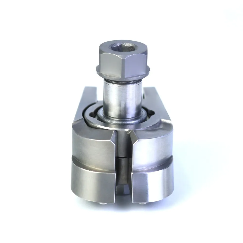
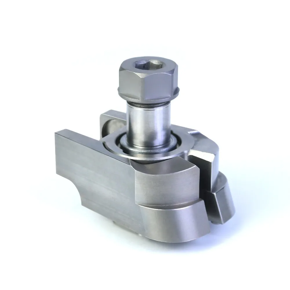
The component shown is a precision-machined split clamping body with a central shaft or bore interface. The visible design includes a divided outer body, stepped cylindrical surfaces, an annular shoulder around the central shaft area, machined split faces and a top fastening or drive feature. Additional views show side openings and mounting-related geometry.
This configuration may be used where a component must locate, clamp, support or interface with a shaft or another mechanical assembly. The exact product function cannot be confirmed from photographs alone. Depending on the approved design, the part may require turning for cylindrical features together with milling for split faces, slots, flats, pockets, mounting areas or other non-rotational details.
For a production-ready quotation, please provide the mating shaft or bore dimensions, clamping method, critical fits, concentricity or runout requirements, thread specifications, material grade, surface treatment, order quantity and required inspection documents.
Built Around Your Drawing
Split clamping components are sensitive to the relationship between the bore, split faces, cylindrical surfaces and fastening features. A small variation in a mating feature can affect assembly fit, clamping behavior or shaft alignment. Our engineering team reviews the complete part definition before production so the manufacturing route and inspection plan reflect the actual design.
The factory accepts common 2D and 3D engineering formats, including STEP, IGS, STL, X_T, PDF, DWG and DXF where applicable. If a complete drawing is not yet available, you can start with photographs, a physical sample, a dimensioned sketch or a functional description for an initial feasibility review.
Product Specifications
| Item | Details |
|---|---|
| Part type | Custom split clamping collar or shaft-interface assembly; final classification subject to drawing review. |
| Manufacturing process | CNC turning, CNC milling and mill-turn machining; exact route is project-dependent. |
| Material | Aluminum, stainless steel, alloy steel, brass/copper, titanium and engineering plastics are available as factory capabilities. Final grade and condition must be specified. |
| Dimensions and threads | To be confirmed from the 2D drawing or 3D CAD model, including bore, shaft fit, thread standard and critical features. |
| General capability | Standard machining tolerance listed as ±0.01 mm; special precision areas may reach ±0.005 mm subject to engineering confirmation. |
| Surface roughness | General factory capability listed as Ra 0.1–3.2; required value is specified by feature and drawing. |
| Surface treatment | Anodizing, black oxide, powder coating, polishing and plating options, subject to material and project requirements. |
| Inspection | CMM, 2D measuring instruments and additional gauges; inspection scope is agreed per project. |
| Quantity | Prototype, low-volume and repeat-production orders are supported subject to drawing, material, process and capacity review. |
Why This Manufacturing Route Works
Mixed cylindrical and prismatic geometry
The pictured component combines rotational-looking surfaces with split sections, flats, openings and other non-rotational details. Turning, milling or mill-turn machining can be selected around the geometry and critical datums.
Engineering review before quotation
The team reviews material, tolerances, threads, surface treatment, quantity and inspection needs before confirming price and timing. Missing information is identified rather than hidden in an assumption.
Prototype-to-production support
Buyers can begin with a prototype or small batch to validate fit and function before moving into repeat production. The confirmed sample date depends on geometry, material and finishing requirements.
Inspection evidence for critical features
The company reports six QA/QC inspectors and five testing instruments, including CMM and 2D measuring equipment. Inspection reports and material certificates can be requested for applicable projects.
Manufacturing Process and Quality Control
- Drawing and DFM review: Engineers review the 2D drawing, 3D model, material, quantity, tolerance call-outs, threads, finish and inspection requirements.
- Material confirmation: The selected grade and condition are checked against the quotation and production documents. Material certificates can be requested where applicable.
- CNC machining: Turning, milling or mill-turn machining is selected according to the bore, split features, datums, threads and production volume.
- Deburring and finishing: Burrs and sharp edges are removed according to the drawing and agreed cosmetic or functional requirements.
- Surface treatment: Anodizing, black oxide, powder coating, polishing or plating can be coordinated according to the material and end-use environment.
- Dimensional inspection: CMM, 2D measurement and additional gauges may be used according to the project inspection plan.
- Final inspection and packaging: Finished parts are checked before export packaging. Special packaging, labeling and documentation can be specified during quotation.
Applications and Industries
The exact application requires technical validation. Based on the visible shaft-interface and clamping geometry, this type of component may be evaluated for industrial equipment, machine tooling, robotics and automation assemblies, motion-control mechanisms, mechanical transmission systems, custom fixtures and equipment modules.
Shenzhen Perfect’s documented target industries include medical equipment, aerospace, automotive, marine, robotics and automation, agricultural machinery, industrial equipment and electronics. Suitability for a specific end use depends on the material, loading, operating environment, regulatory requirements and customer-approved design.
What to Include in Your RFQ
For a clear quotation, please send as many of the following details as possible:
- 2D engineering drawing with dimensions, tolerances, threads and critical features.
- 3D CAD model in STEP, IGS, STL or another compatible format.
- Material grade, heat treatment or temper, and corrosion or temperature requirements.
- Prototype, pilot, per-order and annual quantities.
- Critical bore, shaft fit, concentricity, runout and clamping requirements.
- Surface treatment, color, coating thickness, roughness and cosmetic requirements.
- Inspection reports, FAIR, CMM data, material certificates or compliance documents required.
- Packaging, marking, target delivery date and destination country.
If you do not yet have a complete drawing, send photographs, a physical sample, a dimensioned sketch or a functional description. The engineering team can identify the missing information before the final quotation.
Why Choose Shenzhen Perfect Precision Products?
Shenzhen Perfect Precision Products Co., Ltd. is a custom OEM/ODM manufacturer established in 2012 in Shenzhen, China. The supplied company information identifies 79+ machines, more than 100 professional staff and monthly output capacity exceeding 300,000 pieces. Core services include CNC machining, injection molding, sheet metal fabrication, casting, forging and rapid prototyping.
The factory supports CNC milling, CNC turning and mill-turn machining for metals and engineering plastics. General capabilities listed in the company knowledge base include ±0.01 mm standard machining tolerance, ±0.005 mm in special precision areas and Ra 0.1–3.2 surface roughness, subject to part geometry and project confirmation.
The supplied documentation confirms ISO 9001:2015 and ISO 13485:2016 quality management certifications. It also identifies six QA/QC inspectors and five testing instruments, including CMM and 2D measuring equipment. Project-specific inspection scope, certificate requirements and delivery dates are agreed during quotation.
For buyers managing several component types, the broader one-stop capability can coordinate CNC-machined parts with molded parts, sheet-metal components or other manufactured items. Each component remains subject to its own drawing, specification and inspection requirements.
Frequently Asked Questions
Can you manufacture this split clamping collar from our drawing?
Yes. Send a 2D drawing, 3D CAD model, sample or dimensioned sketch so the engineering team can confirm the process route, material, tolerances and quotation scope.
Which materials are available?
Listed capabilities include aluminum alloys, titanium alloys, stainless steel, alloy steel, brass, bronze, copper and engineering plastics. The final grade, temper and heat treatment must be approved for the project.
What tolerance can you achieve?
The general factory capability lists ±0.01 mm standard machining tolerance and ±0.005 mm for special precision areas. Actual tolerance depends on the material, feature, geometry and inspection method.
Can you make prototypes and small batches?
Yes. Prototype, pilot, small-batch and repeat-production work is supported subject to drawing, material, process and capacity review. Simple CNC prototypes may be completed in 1–3 days; the confirmed schedule is project-dependent.
Can you provide surface treatment and inspection reports?
Anodizing, black oxide, powder coating, polishing and plating options are available subject to material and specification. Inspection reports and material certificates can be requested during quotation.
How do you protect customer drawings?
Customer drawings and product information are treated as confidential business information. NDAs can be arranged upon request, with project access restricted to the relevant team.
Ready to Review Your Custom Component?
Send your drawing, 3D model, sample photos or functional requirements. We will review the material, critical dimensions, clamping features, finish, inspection needs, quantity and target schedule before confirming the quotation.


