
Precision CNC Machined Gear Shafts: Material, Tolerance & Surface Finish Explained
An engineer’s reference for sourcing teams evaluating custom gear shaft components — from alloy selection to dimensional control and post-processing.
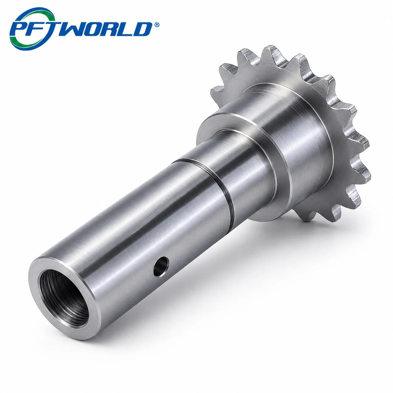
Gear shafts sit at the center of torque-transmitting assemblies — in conveyors, gearboxes, pumps and automation lines. A shaft that looks identical to spec on paper can still fail in service if material, tolerance stack-up, or surface treatment is chosen incorrectly. This guide breaks down the four decisions that determine whether a CNC gear shaft performs reliably under load.
1. Material Selection for Gear Shafts
Material choice drives fatigue life, wear resistance, and machinability. The gear shaft shown above is a turned-and-milled 303 stainless steel part with an integral sprocket-style gear section and a threaded bore — a common configuration for food, medical, or corrosion-exposed drive assemblies.
2. Dimensional Tolerance & GD&T
General vs. Critical Tolerances
Non-critical dimensions are typically held to ISO 2768-m/f general tolerance classes. Features that mate with bearings, bushings, or gear hubs — bore diameter, shaft OD at the bearing seat, and concentricity between the shaft and gear section — should carry tighter, explicitly called-out tolerances, commonly ±0.005–0.01 mm on precision shafts.
Why Concentricity Matters More Than Diameter
On a stepped shaft like the one pictured, runout between the shaft axis and the gear bore is often the real failure driver — not the diameter tolerance itself. Specify total indicated runout (TIR) on the drawing rather than relying on diameter tolerance alone to control alignment.
3. Surface Finish & Post-Processing
4. Quality Inspection Workflow
First-Article & In-Process Checks
A disciplined gear shaft program runs CMM inspection on first articles, with AQL-based sampling (commonly 1.5–2.5) through production runs. Critical features — bore thread fit, gear tooth profile, and shaft straightness — should be checked every batch, not only at first-article stage.
Frequently Asked Questions
What tolerance can CNC machining realistically hold on a gear shaft?
On a standard 3-axis CNC lathe/mill setup, ±0.01–0.02 mm is routinely achievable on turned diameters; critical bearing seats or press-fit bores often need grinding to reach ±0.005 mm.
Is stainless steel or alloy steel better for a gear shaft?
Choose stainless (303/304) when corrosion resistance or hygiene is required; choose alloy steel (4140) when maximum fatigue strength and heat-treat hardness are the priority and the environment is dry or coated.
Do integral gear shafts need separate heat treatment for the teeth?
Often yes. Because the shaft body and gear section share one blank, localized induction hardening or selective carburizing is used so the teeth gain wear hardness while the shaft core stays tough.
How is concentricity between the shaft and gear verified?
With a CMM or dial-indicator setup measuring total indicated runout (TIR) between the shaft’s bearing-seat axis and the gear bore/pitch diameter — this should be specified as a drawing callout, not assumed.
What inspection report should I request from a CNC supplier?
Ask for a dimensional inspection report (CMM or manual) covering every drawing-critical feature, plus material certification and, where applicable, hardness test results for heat-treated zones.
Need a DFM Review for Your Gear Shaft Drawing?
PFTWORLD’s engineering team reviews tolerance stack-up, material fit, and post-processing before quoting — so your first article is production-ready.
Post time: Oct-20-2026


